
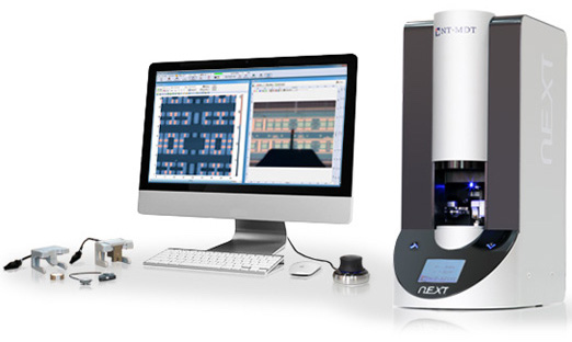
NT-MDT NEXT Atomic Force Microscope
Multifunctional scanning probe microscope supporting AFM and STM for nanoscale imaging and analysis. Enables high-resolution topography, electrical, and mechanical measurements.
Location: SE1 153E
Noncontact/Semicontact probes available:NSG10 and NSG30
Contact Probes available: CSG10 and CSG30
Learning Center / Introduction to AFM
Challenges and Solutions in Practical Atomic Force Microscopy
This instrument allows for extremely high-resolution imaging.
Mode: Contact, semi-contact and non-contact AFM
Scanning Probe Microscope (SPM) — NT-MDT Solver NEXT
The NT-MDT Solver NEXT Scanning Probe Microscope (SPM) is a multifunctional nanoscale characterization system capable of performing both Atomic Force Microscopy (AFM) and Scanning Tunneling Microscopy (STM). It enables high-resolution surface imaging, material property analysis, and nanoscale manipulation across a wide range of environments.
Key Features
- Dual-mode system: AFM and STM with interchangeable heads
- High-resolution scanning (up to ~100 × 100 µm scan area)
- Sub-nanometer vertical resolution and low noise performance
- Automated laser alignment and cantilever detection
- Integrated optical microscope for sample positioning
- Environmental compatibility (air, liquid, and controlled conditions)
- Support for multiple advanced SPM techniques
System Capabilities
- Topography Imaging: High-resolution surface morphology
- Electrical Characterization: STM, conductive AFM, Kelvin probe
- Mechanical Properties: Force spectroscopy, nanoindentation
- Advanced Modes: Phase imaging, magnetic force microscopy (MFM), electric force microscopy (EFM)
- Nanofabrication: AFM/STM lithography capabilities
Typical Operation Workflow
- Mount sample on holder and secure on stage
- Install AFM probe or STM tip
- Perform initial approach using optical microscope
- Align laser and detection system (AFM mode)
- Select scan area and set parameters
- Perform scan and collect data
- Analyze results using control software
Training and Usage
Users are trained on:
- Sample preparation and mounting
- Probe installation (AFM cantilever / STM tip)
- System alignment and approach procedures
- Scan parameter selection and optimization
- Data acquisition and analysis
Safety Considerations
- Laser-based detection system — avoid direct exposure
- Sensitive piezo scanner — avoid mechanical shocks
- Electrical safety and grounding required
- Maintain stable environmental conditions (vibration, temperature)
Image Analysis Software — NT-MDT Image Analysis P9
Comprehensive software for processing and analyzing SPM data (1D, 2D, 3D). Supports surface roughness, FFT, correlation, and advanced image processing with integrated measurement and reporting tools.
The Image Analysis P9 software is a comprehensive data processing and analysis platform designed for handling Scanning Probe Microscopy (SPM) data, including 1D, 2D, and 3D datasets. It supports advanced visualization, filtering, and quantitative analysis of surface properties.
Key Features
- Supports 1D, 2D, and 3D SPM data visualization
- Integrated tools for filtering, transformation, and image editing
- Advanced measurement tools (distance, angle, profiles, sections)
- Multi-frame data handling with hierarchical structure
- Customizable interface with toolbars, filters, and analysis modules
- Export and reporting capabilities (including MS Word format)
Analysis Capabilities
- Surface Roughness Analysis: ISO/ASME standard parameters
- Fourier Analysis (FFT): Frequency and spectral analysis
- Correlation Analysis: Auto-correlation and structural functions
- Grain/Feature Analysis: Segmentation and morphology
- Profile & Section Analysis: Line scans and cross-sections
- Data Processing: Filtering, leveling, background subtraction
- Statistical Analysis: Histogram and distribution analysis
Typical Workflow
- Import SPM data (MDT or compatible formats)
- Visualize data in 1D/2D/3D viewer
- Apply filters and corrections (flattening, noise reduction)
- Perform measurements (line, angle, markers)
- Run analysis modules (FFT, roughness, grain analysis)
- Export processed data and generate reports
Training and Usage
Users are trained on:
- Data import and visualization
- Use of analysis and filtering tools
- Measurement techniques and interpretation
- Data export and reporting
System Notes
- Designed primarily for NT-MDT instruments but supports general SPM workflows
- Includes modular interface (Frames Tree, Analysis Area, Toolbars)
- Provides real-time visualization and interactive measurement tools
Detailed Safety Considerations – Atomic Force Microscope (AFM) / Scanning Probe Microscope (NT-MDT Solver NEXT)
The AFM/SPM system is a high-precision nanoscale characterization instrument involving hazards related to laser exposure, delicate probes, electrical systems (STM mode), piezoelectric scanners, and mechanical positioning systems. While generally low-risk compared to fabrication tools, improper operation can result in probe damage, sample damage, equipment misalignment, and inaccurate data. Only trained and authorized users may operate the system.
Laser Safety (AFM Detection System)
- The AFM uses a laser-based detection system to monitor cantilever deflection.
- Avoid direct eye exposure to the laser beam or reflected paths
- Never look directly into the laser source or alignment path
- Ensure laser is properly aligned within enclosed optical path
- Do not bypass protective covers or safety features
- Use caution during laser alignment procedures
Probe and Cantilever Safety
- AFM probes (NSG10, NSG30, CSG10, CSG30) are extremely sharp and fragile.
- Handle probes only with appropriate tools (tweezers, holders)
- Do not touch probe tips directly
- Avoid sudden movements during probe installation
- Use appropriate mode (contact, semi-contact, non-contact) for sample type
- Stop immediately if probe crashes or abnormal signals occur
Sample Handling and Compatibility
- Improper samples can damage both the probe and system.
- Ensure samples are clean, dry, and securely mounted
- Avoid loose particles, dust, or contamination
- Do not scan sticky, soft, or poorly adhered materials without proper settings
- Ensure sample surface is compatible with selected imaging mode
- Use conductive samples or grounding when operating in STM mode
Piezo Scanner and Mechanical Safety
- The system uses high-precision piezoelectric scanners for nanoscale movement.
- Avoid mechanical shocks or vibrations to the system
- Do not apply force to the scanner or sample stage
- Ensure proper approach settings to prevent probe crash
- Keep hands clear during automated approach and scanning
- Maintain stable environmental conditions (low vibration, stable temperature)
Electrical and STM Mode Safety
- In STM mode, the system involves bias voltage and tunneling current.
- Ensure proper grounding of sample and system
- Do not touch electrical contacts during operation
- Verify correct voltage settings before initiating STM measurements
- Avoid operation with damaged cables or exposed connections
Approach and Scan Safety
- Improper approach can lead to probe crash and system damage.
- Always use controlled, automated approach procedures
- Monitor probe-sample distance carefully
- Start with conservative scan parameters
- Avoid scanning large height variations without proper setup
- Use test scans when working with unknown samples
Contamination Control
- AFM measurements are highly sensitive to contamination.
- Use only clean, approved samples and substrates
- Avoid introducing oils, dust, or residues
- Clean sample holders and stage regularly
- Prevent cross-contamination between different materials
Environmental Stability Requirements
- AFM performance depends on stable environmental conditions.
- Avoid vibration, air drafts, and acoustic noise
- Maintain stable temperature during measurements
- Do not operate near heavy equipment causing vibrations
- Ensure system enclosure is properly used if available
Software and Data Integrity (Image Analysis P9)
- Verify correct data acquisition settings before scanning
- Avoid modifying raw data without preserving original files
- Use appropriate filters and corrections during analysis
- Ensure proper data backup and storage
PPE Requirements
- Lab garments (as required for the area)
- Safety glasses (recommended during setup)
- Gloves when handling samples and probes
Operational Safety Checks (Pre-Run)
- Sample is clean and securely mounted
- Correct probe is installed and aligned
- Laser alignment is properly configured
- Scan parameters (mode, size, speed) are appropriate
- Environment is stable (low vibration, controlled temperature)
- Electrical connections are secure (especially for STM mode)
Post-Operation Safety
- Retract probe safely from sample surface
- Remove sample carefully
- Store probe properly if reusable
- Clean stage and workspace if necessary
- Save and back up data
- Log system usage and report any issues
Waste Handling and Contamination Control
- Dispose of used probes and contaminated materials in designated containers
- Do not leave debris on stage or sample holder
- Maintain a clean and controlled measurement environment
Emergency Procedures
- Probe crash → stop system immediately and notify staff
- Laser misalignment or exposure → stop operation and secure system
- Electrical issue → power down and report
- Excessive vibration or instability → stop measurement
- Software/system malfunction → halt operation and notify staff
- Do not resume operation until the system has been inspected and cleared.
General Cleanroom Conduct
- Use only approved samples and measurement techniques
- Handle probes and components with extreme care
- Maintain strict cleanliness and environmental stability
- Avoid unnecessary adjustments or force
- Report issues promptly
Atomic Force Microscope (AFM) Training – Session Coverage
During the training session, the following topics and steps will be covered:
-
Overview of AFM principles (contact, semi-contact, and non-contact modes)
-
System components (probe/cantilever, laser detection system, scanner, stage, control software)
-
Sample requirements and preparation (clean, compatible, properly mounted)
-
Probe selection and handling (NSG10, NSG30, CSG10, CSG30)
-
Probe installation and laser alignment procedures
-
Approach mechanism and safe probe engagement with sample surface
-
Scan parameter setup (scan size, speed, setpoint, feedback settings)
-
Performing surface imaging and data acquisition
-
Basic AFM modes and their applications (topography, phase imaging)
-
Introduction to advanced capabilities (electrical, mechanical measurements, STM mode overview)
-
Data visualization and analysis using Image Analysis P9 software
-
Saving, exporting, and documenting measurement results
-
Common issues (probe crash, noise, drift, poor imaging) and basic troubleshooting
-
Safe probe handling, system care, and environmental considerations
-
Cleanup, contamination control, and system readiness
Note: Training is conducted using standard samples and facility-approved probes, focusing on safe operation and understanding of nanoscale imaging; users are responsible for carrying and advancing their own research projects.
